Patent Pages
by Ray Klingensmith
Reprinted from "INSULATORS - Crown Jewels of the Wire", April 1979, page 18
The Johnson Watson Patent
The insulator embossed
"Johnson & Watson"//"PAT D" certainly is an interesting
one, with many unusual characteristics, and some unanswered questions concerning
the inventors. At this time I personally do not have a patent copy on this item.
There are two unusual and interesting features on this insulator. The first is
the very unusual top, which appears to have been designed to hold a line wire
without the use of a tie wire. The second is the peculiar interior threads.
This
insulator is similar to the Harloe patent in that it has "fingers" at
the top. However, rather than three "fingers", the Johnson &
Watson has two, each facing in the same direction. Instead of another one facing
the opposite direction between these two, as with the Harloe, there is a taller
pointed projection which is tapered downward (see fig. 1).
Figure 1 is a drawing
which shows a top view of the insulator. The insulator appears to have been
designed in a manner so that a person could position the line wire directly
above the insulator, place the wire at the top of the middle projection and
press it downward along the sloping shoulder, and at the same time slightly bend
the wire so as to allow it to go under the other two "fingers". The
dotted lines in figure 1 show where the wire, once installed, would be held
under the fingers. The center projection is in a position to slightly kink the
wire when in place. This puts enough pressure on the wire to keep it from
"popping out" of place.
Figure 2 shows a front view of the insulator.
Notice the very unusual location of a mold line which goes around the insulator
approximately one half inch from the base. This is a very difficult design to
draw, and I hope the sketches are clear enough to show what the item really
looks like. The front view shows the insulator to appear somewhat similar in
design to the "pony" style, like the CD 102. As can be seen in the
drawings and the photo in this article, the insulator with its peculiar design
would be very prone to damage. Forcing a wire to have a slight bend in it when
in place would cause considerable pressure on the fragile glass, especially
during high winds or sudden changes in temperature when the wire would expand
and contract. This characteristic probably explains the design's limited use and
accounts for only one of these being known to exist.
I was talking with another
collector a couple years ago who felt he saw a bluish-aqua one at one of the
earlier Toledo, Ohio shows. The one known to collectors is a light green-aqua.
This suggests a possibility of another, which may be the case. However, the
green-aqua one was purchased by a collector after it was taken to one of the
Toledo shows, so I feel it is the same one. Perhaps different light sources can
explain the mystery. Anyone out there in collectors-land feel different about it?
There are always a few surprises turning up.
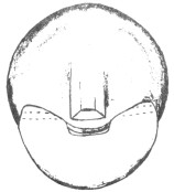
Fig. 1: Top view of Johnson & Watson. Note dotted lines which
show the position of a line wire after installation. |
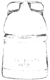
Fig. 2: Front view. Notice
similarity to CD 102 "pony" style and unusual location of the mold
line near the base. |
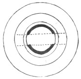
Fig. 3: Base view showing unusual location of mold line from
edge of base to top of interior. |
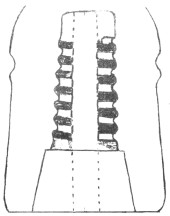
Fig. 4: Cross section showing segmented threads
and interior mold lines. (Dome area not included) |
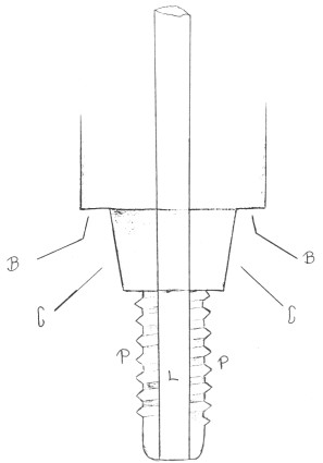
Fig. 5: Type of plunger believed to have been used in making the J & W. The stem (L) could be
withdrawn for easy removal of the plunger. |
As stated earlier, the top
area of the insulator is only one of the interesting characteristics, the other
being the unusual threads. Without any patent copies, it's hard to say if the
name Johnson & Watson refers to one or two patented features. Both names
could be for the top design; or one could be for the top, and the other for the
method of forming the threads in the insulator. I've never seen another
insulator in any style with the same type of segmented threads as the Johnson
& Watson. All other segment threaded insulators were either the type found
in Boston Bottle Works insulators, or the type found in the National Ins. Co.
items. Both of these types had just the threads formed in "segments"
in the molding process. The interior of the insulator between the base of the
threads and the base of the insulator was formed by a solid circular plunger
(See "A" in fig. 6). In other words, what I'm saying is the threads
(in National items) were formed by a process where the threaded part of the
plunger would contract so it could be removed from the insulator. The part of
the plunger which formed the inner part of the skirt, between the threads and
the base, did not contract. It was a stationary piece which simply lifted out of
the insulator after forming.
Large Image (137 Kb)
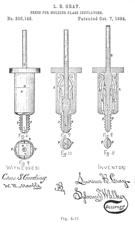
Fig. 6-11 Drawing from
Lawrence Gray patent specification showing a device similar to fig. 5. |
The Johnson & Watson is different in that
respect. Both the threads and the skirt's interior section were formed in a
segmented operation (see figures 3 and 4). Figure 3 shows a base view of the
insulator. The dotted lines show the "mold lines" which run parallel
to each other from the base all the way up to, and across the top interior.
Figure 4 is a cross-section of the insulator (dome area not included) which
shows the segmented threads and interior mold lines.
Figure 5 shows a drawing of
the type of plunger I believe was used to make the J & W interior. The
entire fully constructed piece could be inserted into the mold, the glass
insulator being formed. The letters "B" show the part which forms the
base of the insulator, "C" shows that part which forms the skirt
interior, "P" shows the two threaded sections, and "L" shows
a rectangular stem which could be withdrawn, allowing the two parts (P,P and C,C)
to come together and be withdrawn from the insulator. This process allows the
maker to simply lift the plunger out, instead of turning it out, as was required
in other methods. This is allowed due to the fact that the two parts are
contracted together, which allows the plunger to clear the threaded interior
formed in the insulator, without disturbing said threads.
There was a patent
issued to Lawrence B. Gray, of Boston, Mass. on Oct. 7, 1884, which is very
similar to figure 5 (see figures 6-11 for a copy of the specifications from the
Gray patent). I personally feel the Johnson & Watson was not made under the
Gray patent. The main reasoning behind this is because Gray was granted two
different patents on Oct. 7, 1884. The first, #306,146, was filed on March 13,
1884. The second, #306,147, was filed April 28, 1884. Both are identical, with
the exception that the latter was a process which formed a fully threaded
insulator instead of a segmented one. I believe the second idea was thought up
right after the March 13 application, and therefore an additional patent was
applied for before another party got the same idea. For that reason, if Gray
came up with the idea to form the entire interior with a "segmented
operation", I believe he would have included it in the specifications, or
had a third patent issued, which, to my knowledge, was not done.
Figures
6 through 11 show the drawings from the Gray patent #306146. Figure 6 is the
complete plunger with the stem, "L", inserted. The solid portion I
referred to earlier is shown by "A". Figure 7 is a vertical cross
section. Figure 8 is a vertical cross section showing the stem pulled upward,
letting the segments come together, allowing the plunger to be pulled upward and
removed from the mold without the necessity of turning it out. Figures 9, 10,
and 11 are horizontal sections of figures 6, 7, and 8 respectively.
|
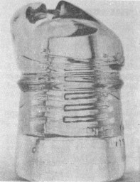
Photo of the Johnson & Watson showing unusual segmented threads
and a side view of the dome area.
|
Without any
patent copies, it's really hard to say whether the Johnson & Watson was made
under the Gray patent. If both Johnson's and Watson's names appear on the patent
for just the top, then I'd say the chances of Gray being involved would be
better. The insulator looks like something which would have been made in the
1890's. The "pony" style, which it resembles, was introduced long
before that. Segmented threads, which were used in the 1870's and 1880's, it
seems to me, would be outdated by the 1890's, with many new manufacturing
techniques taking place along the way. The main reason for making segmented
threads in the first place was to avoid making crude and deformed threads, which
occurred when the plunger was turned out. The improvements of the 1880's, for
the most part, cleared up that problem on fully threaded insulators. So it's
very hard to date it.
From what I've gathered, the Johnson & Watson was
found in northeastern Ohio. I hadn't planned on covering this particular item
at this time, and would have done a little more research had I more time.
However, my own personal laziness on researching another patent led me to doing
this one. If anyone has any info on this item you would like to share, let me
hear from you.
By the time you're reading this, I'll probably be working on the
July column. I plan to cover the Oakman, Oct. 15, 1872 patent, which involves
the Boston Bottle Works insulators. I'd like to set a goal at this time of at
least ten pages on that subject. My deadline for gathering all the material will
be May 10, so if you have anything that could be included, please contact me. I
want it to be the best article of any I've done, so let's get together and do
one together. Also, I'd like some black and white photos of insulators with drip
points for a future column. Come on, folks, let's help out!
Just thought I'd add
that I was honored to be able to see John and Carol McDougald's fabulous
collection recently at their lovely home. I couldn't believe all the rare and
beautiful pieces they've gathered over the years. So many pieces I never knew
even existed! Thanks to both of you for a very enjoyable time, It was quite a
day.
|

)
)
)
)
)
)